STIRLING ENGINE
Inside a Stirling engine is performed a heat cycle through a working gas. The Stirling engine does not contain valves. This fact, in first view, its is done very simple machine, but its thermodynamic design is done very difficult (Stirling engine cycle is not can divided on more parts, which could be solved separately, similar as e.g. can be to divide cycle of a steam piston engine).
Using of Stirling engine
The Stirling engine is known almost 200 years. Inside the Stirling engine is performed the heat cycle and work is outputted from the engine in form a rotating shaft. The Stirling engine is a piston engine with external heat transfer (heat is inputed/outputted to/from the cycle through heat-transfer surfaces). This property theoretically allows the Stirling engine use any source of the heat.
The Stirling engine (or its older name hot-air engine) was patented by Robert Stirling (1790-1878) in year 1816. First prototype was built two years later [3]. This prototype had two pistons stacked inside one cylinder and had not heat-transfer surface outside cylinder. Later, other inventors patented additional types engines with similar principle and air as the working gas, therefore the Robert Stirling's engine is called Stirling engine. This engine is different from other heat-air engines simple design without valves.
![The first Stirling engine, [3].](objekty/747.gif)
John Ericsson (1803-1889) made a wide comparison between his hot-air engine, which contains valves (current this engine is called the Ericsson engine) and the Stirling engine at second half 19th. Over time he came to the conclusion, that the Stirling engine is simpler and reliabler than his type engine and his engine was not being developed next time [4]. The Stirling engine was used as a substitution of the steam piston engine about small power (about to 5 kW) during 19th century. The Stirling engine was gradually displaced by internal combustion engines, because these engines was being made better and has bigger the ratio power/weight. Subsequently the Stirling engine had been used only for application with small requirements on power, efficiency or for cases which required a low maintenance, higher reliability operation and non-precious fuels. A typical example for that time is a development mobile Philips Stirling generator [5], which was done from 1940 to 1950. These generators was made several hundreds:
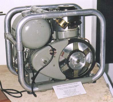
The nominal electric power output of this generator was 200 W at mean pressure of the working gas (air) 1,35 MPa. The picture from [5].
Due to the oil crisis during 70th the 20th century was contemplated the Stirling engine as an engine for drive of the personal cars, because it can use other fuels than petroleum fuels. This idea performed Ford company. At first was contemplated Philips 4-65 Stirling engine, but at final the Ford company commissioned the United Stirling company by the development of the personal car Stirling engine. The United Stirling company is Swedish company. The operational tests shown inappropriateness of the Stirling engine as the drive of the car. The capabilities regulation of power and speed was disappointments and these capabilities are the most significant for the personal car. Through these reasons this development was end till today [6]:
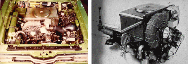
On the figure is a prototype of the Stirling engine V4X35. The engine power reached 40 kW, working gas was hydrogen. This prototype drove 10000 km during trials. Next prototype V4X36 was installed inside the racing car Porsche Bergspider. This car reached 135,88 km·h-1 mean speed on a control stretch (10 km) and maximum speed was 200 km·h-1, it is the most speed for car with the Stirling engine. The pictures and information from [6].
Company United Stirling used experiences with the development of the Stirling engine car for a development new Stirling engine for stationary application. The start of this development was at 80th the 20th century and this engine was called United Stirling V 161 (α-configuration, the V-cylinders, volume of one cylinder 161 cm3, working gas Helium). This engine is able a stepless regulation of its power output through change of pressure and temperature of the working gas and maximum power is about 10 kW. In currently it is the most technologically advanced Stirling engine on the market.
At last years the Stirling engine is associated with a term cogeneration in relation to a combined heat and power of small units for domestics. This application is called domestic cogeneration. The Stirling engine are stiller and its vibration are smaller inside this unit at comparison with the combustion engines:

left cogeneration unit Cleanenergy with Stirling engine V 161, electric power output from 2 to 9 kWe, heat power output from 8 to 24 kWt (2013), fuel Natural gas; right cogeneration unit WhisperGen with Stirling engine, electric power output from 0,8 to 1,2 kWe, heat power output 8 kWt, four-cylinders engine, fuel Natural gas. Photo: [17].
At current time the development of the Stirling engines is focused on a field of small unit for transformation renewable resources on generation of electric energy about 50 kWe power output. The unit with the Stirling engine that use biomass is able to higher efficiency than the unit with classic a steam cycle about the same power:

left one from prototypes of development project of Stirling engine for Biomass use. This project is cooperation Denmark and Swedish universities. Prototype SM3D, working gas He, electric power 35 kWe, mean pressure of working gas is 4,5 MPa. Electric generator is closed inside hermetic casing with engine for reduce requirements on seal tightness of piston rod. Engine is double-acting and four-cylinders [11]. right cogeneration unit with a Stirling engine from company Öko-Energiemaschinen Vertriebs GmbH. This unit use the pellets as fuel. The working gas: nitrogen, electric power output 1,5 až 3 kW, heat power: 4,5 až 10,5 kW, electric efficiency: 20 až 25 % [18].
The generation of electric power of solar radiation through the Stirling engines is very effective. However, most projects are still only in development stage. In these cases the Stirling engine with generator is mounted to the focus of a parabolic reflector through one or more beams, because the power output these unit are only from 5 to 50 kWe. A sytem of parabola-unit follows the Sun through a rotating vertical and horizontal axis. In focus of the parabola is heater of the engine, where is temperature from 800 do 900 °C. The cooling of the engine is performed by a water cooler with fan, which is localized on opposite side of the engine than is the heater. The cooling can be performed also through special cooling loop, where a cooling liquid is led by tubes fixed to the beam. Problems are related to orientation of the engine, which is not horizontal (lubrication, seal of the rods...) and a overheating of the heater is also dangerous:

left The experimental solar unit EuroDish-the unit SOLO with the Stirling engine V 161 be located in the focus of the parabolic reflector. Electric power this application is 7,9 kW at solar power 850 W·m-2, efficiency conversion of solar power on electric power is 15,3% [10]; right experimental set Stirling engine V180-parabolic reflector of Strojírny Bohdalice, a.s. for transformation solar energy to electric energy. This engine and the reflector are their product. Localization Bohdalice (CZ). This engine is α-configuration, working gas He, 10 kWe, 25 kWt.
Currently be being developed the Stirling engine unit for space probes [12] and small power unit for extraterrestrial bases [13]. For these cases is assumed a radioisotope unit as heat resource (SRG-Stirling Radioisotope Generator). This system has an advantage of higher efficiency about 26 % (at cooling of the working gas on 50 °C) opposite thermoelectric unit about 8 %:
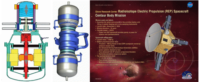
left Stirling engine with free piston on hot side and with linear generator about 55 W* power that being tested in NASA [8, p. 105]; in the middle two Stirling converters (2x55 W) that are located opposite each other. Between them is placed NaK loop (sodium-potassium) for transfer heat from radioisotope unit [9]; right picture of space probe with ion thruster that use electric power from three SRG units [12].
This engine is β-configuration (a definition of the Stirling engine configuration there is below). This engine has free piston on the hot side (the piston has not kinematic connection with the piston on the cold side, its move is realised by two packs of leaf spring). A core of the linear generator is moved ba the piston on the cold side. The piston on the cold side does a reciprocating motion between the buffers through two volumes spring. The cylinder on the hot side has a double-jacket casing. The heater and the regenerator are located inside the gab between the jackets of the cylinder casing. The cooler is located upper the buffer on the circuit of the cylinder between the hot side and the cold side of the engine. This engine is produced by Sunpower Inc. company [14]. Much more versions this engine are used inside cogeneration units about 1 kW power on fossil fuels. Nevertheless these applications contain problems with very small heat transfer surface, because this type of the Stirling engine is primary constructed for case a heating medium with high heat-transfer coefficient. This fact is compensated through high temperature of a combustion gas on a output from a combustion chamber and small electric efficiency (only about 4 %). Also there is a problem on the cold side, because a cogeneration unit is produced a hot water and working gas is cooled on higher temperature than on a space probe application.
Stirling engine and its principle
The Stirling engine contains three fundamental parts – the heat side, the cold side and the regenerator:
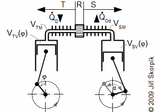
T hot side; R regenerator; S cold side. VTV [m3] cylinder volume on hot side; VTM [m3] dead volume on hot side; VSM [m3] dead volume on cold side. Q•D [W] heat flow to engine (heating); Q•Od [W] rejection heat flow of engine (cooling); φ [°] angle of rotation; α [°] phase angle of hot side volume variation to cold side volume. The volume between the pistons is the working volume of the engine.
The Stirling engine is a reciprocating machine that produce work through change the working volume and change the pressure, temperature of the working gas. The working gas is displaced between the hot side and cold side across the ragenerator by the pistons. The move of the pistons (both pistons are kinematic interconnected) changes zhe working volume. During displaced of the working gas inside engine (between the hot and the cold side) is changed the mean temperature and pressure of the working gas inside the working volume. An internal work of the Stirling egine is equivalnet to a variation of pressure during change of working volume (p-V diagram).
Inside the regenerator is performed a regeneration of heat through a temperature gradient between the hot and the cold side. The working gas is cooled during its flow from the heat side to the cold side of the engine, the heat is transfered from the working gas to a matrix of the regenerator (more often it made up a thin steel wire). If the temperature of the working gas is decreased then the temperature of the matrix regenerator is increased (a charging of the regenerator). The working gas is heating during its flow from the cold side to the hot side of the engine, the heat is transfered from the matrix of the regenerator to the working gas. The temperature of the matrix is decreased and the temperature of the working gas is increased (a discharge of the regenerator). The benefits of the regeneration of heat is a saving of the heating heat. Thanks to the regeneration heat is smaller requirement heat flow to the engine PT and the heat flow from the engine PS. The regenerator through this process increasing thermal efficiency of cycle.
The kinematic connection of the pistons is very significant. The phase angle α is function type move of the pistons (linear move, sinusoidal move...) and a construction respectively a configuration of the engine. In case of the crank mechanism usually is the phase angle from 90° to 105°.
Main configurations of Stirling engine
The configurations of the Stirling engine are distinguished through a way interconnection of the hot and cold side. For case α-configuration the change of the volume of the hot side is influenced by the piston on the hot side only, and the change of the volume of the cold side is influenced by the piston on the cold side only. For case β-configuration the volume of the hot side is influenced by the piston on the cold and hot side. The difference between γ-configuration and β-configuration is that the volume on the cold side can not be zero even if the dead volume is zero. Double-acting Stirling engines are similar as the α-configuration, where the volume under the piston on the cold side is the cold side of the neighboring cylinder that are together interconnected (from principle of the Stirling engine is evident that there is minimum number of the cylinders is 3, but usually are used 4 to 6-cylindrical double-acting engines):

(a) α-configuration; (b) β-configuration; (c) γ-configuration; (d) double-acting α-configuration. The figure from [19].
Between individual configurations there are only construction differences. Their technical properties are very similar and it is not known if any configuration is better from others. The α-configuration is the most popular because this construction is the most simple construction of all configuration:
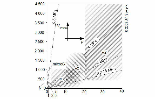
VVT, max [cm3] stroke volume of cylinder on hot side; Psp [kW] power output on coupling; pst [MPa] mean pressure of the working gas inside engine; αx multi-cylinder α-configuration; α2 double-acting configuration; microS small Stirling engines. The diagram is in relation to current situation. The figure from [19].
Fundamentals of Stirling engine design
The α-configuration engines usually have a buffer tank. The buffer tank connects the spaces under the pistons and it decreases the pressure ratio inside this space (in ideal case pressure is constant here and it is equal the mean pressure of the working gas inside the working volume). High pressure ratio in this space (inside the buffer tank) causes problems with higher stress of the engine construction and its the piston rings, also it is influenced the torque:
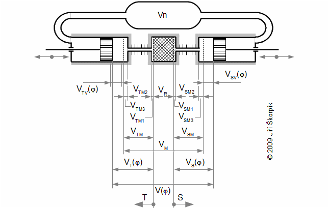
VT(φ) [m3] volume of hot side of engine; VS(φ) [m3] volume of cold side of engine; V(φ) [m3] working volume of engine; VM [m3] dead volume of engine; Vn [m3] volume of buffer tank. The figure from [19].
Boundary of individual volumes of a real engine are shown on next figure:
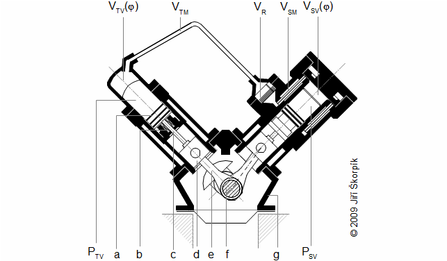
a piston rings; b stuffing box of piston rod; c piston rod; d piston rod guide; e connecting rod; f crankshaft with balance; gcasing of the crankshaft; PTV piston of hot side of engine; PSV piston of cold side of engine. This figure is simplified picture only without buffer tank. This engine was used for research of the Stirling engine cycle and some construction parts. This research was done by Tedom a.s. the years 2002 to 2004.
The Stirling engine contains normal machinery components as the connecting rod or the crankshaft. The construction these parts and a calculation of theirs move is similar as in case a steam piston engine (see the articel Essential equations of crank mechanism of steam engine). Other components of the Stirling engine can be non-typical (or their working conditions) e.g. the regenerator, the heater and cooler.
Regenerator of Stirling engine
The matrix of the regenerator is usually made up of wire about diameter less than 0,1 mm arranged in a grid or chaotically and baked, but there are the matrix created from thin plate also:

a; b grid matrix; c chaotically matrix. rR [1] porosity of regenerator; Vmat [m3] volume of matrix (clean volume of wires); VR,abs [m3] total volume of regenerator (sum of volume of matrix and dead volume of regenerator). Figures from [15, p. 230].
A suggestion of the regenerator design is optimized according three significant requirements: (1) Inside regenerator must be performed regeneration of required amount of heat. – (2) Minimum pressure drop of regenerator. – (3) The regenerator must have minimum volume of its dead volume.
For a calculation of the regenerator (heat-transfer surfaces and the volume of the matrix) is necessary to know the amount of regenerated heat inside regenerator, parameters of flow (mass flow rate through the regenerator) and the temperature difference between the working gas and the matrix of the regenerator. The working gas has variable the velocity flow and its direction inside the regenerator during one cycle. Despite this fact be can used for the suggestion of the regenerator methods, which are used for calculation of steady flow [1, p. 483], [2] with sufficient accuracy. In this case are used mean values of parameters of the working gas, which are necessary for the calculation. The temperature difference between the working gas and the matrix of the regenerator is variable during one cycle (there are running a temperature change of the working gas and matrix of the regenerator) therefore is defined the mean temperature difference:
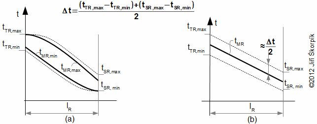
a real plot of temperature of working gas and matrix of regenerator according [3]; b simplified plot of temperature of working gas and matrix of regenerator. tTR [°C] temperature of working gas on hot side of the regenerator; tSR [°C] temperature of working gas on cold side of regenerator; tMR [°C] temperature of matrix of regenerator; lR [m] length of regenerator; Δt [°C] mean temperature between working gas and matrix of regenerator.
Heater of Stirling engine
The heater is heat exchanger with the heat transfer surface through them flows heat to the engine. This heat is usually transfered by a hot combustion gas or sun radiation. For ideal case the heater forms the majority ratio of the dead volume on the hot side of the engine:
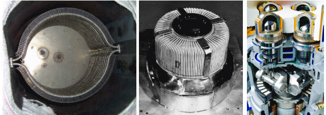
left heater of Stirling engine United Stirling V160, which is made from two rows of finned tubes (this heater for combustion of natural gas); in middle heater from smooth tubes (engine V4X35) [6]; right engine has not heater, transfer of heat is performed through fins of cylinder-intake of combustion gas is in axial direction and output in radial direction (four-cylinders double-acting WhisperGen engine, working gas nitrogen [17]).
Intake of the heat is not steady through the heater to the working gas but it is alternately similarly as inside the regenerator. The temperature of the working gas is changed inside the heater during one cycle. This change is higher than the change of temperature of inner surface of the heater. If the temperature of the working gas is lower than temperature of inner surface of the heater, then heat from the heater to the working gas flows and conversely. It means the inner surface of the heater (only thin depth of the surface) works as the regenerator that is fed more amount of heat to the working gas than receives. This heat that is transmitted "for more" to the working gas during one cycle is the input heat of the engine. The input heat flows to the engine through the outside surface of the heater.
The high change of temperature of the working gas inside the heater are not observed on outside surface of the heater (on inner surface are observed) [16]. It caused through greater damping of temperature change inside matter of the heater. Therefore for calculation of the heat-transfer surface of the heater is used the mean temperature of the working gas inside the heater and the mean temperature of outside surface of the heater (or the mean temperature of the hot gas on outside of the heater). Approximate variation of the working gas temperature respectively its mean temperature inside of the heater is calculated numerically or it can be calculated analytically under simplifying assumptions (see Problem 2 in articel Stirling engine cycle).
Cooler of Stirling engine
The cooler is a surface heat exchanger through them flows heat from the engine, where the heat is usually transferred through a cooling liquid or air. For ideal case the cooler forms the majority ratio from the dead volume on the cold side of the engine:
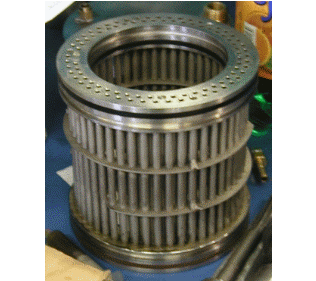
The working gas is cooled unsteady inside the cooler similary as inside the regenerator. The temperature of the working gas is changed inside the cooler during one cycle. This change is higher than the change of temperature of inner surface of the cooler. If the temperature of the working gas is lower than temperature of inner surface of the cooler, then the heat from the cooler to working gas is flowed and conversely. It means the inner surface of the cooler (only thin depth of the surface) works as the regenerator that is fed smaller amount of heat to the working gas than receives. This heat that is transmitted "for more" from the working gas during one cycle is the rejection heat of engine. The output heat is exhausted through the outside surface of the cooler.
The principle of heat transfer inside the cooler is the same as the heater, but the mean temperature of the working gas inside the cooler is higher than the mean temperature of inner surface of the cooler. Approximate variation of the working gas temperature respectively its mean temperature inside of the cooler is calculated numerically or it can be calculated analytically under simplifying assumptions as for the heater.
Energy flows inside Stirling engine
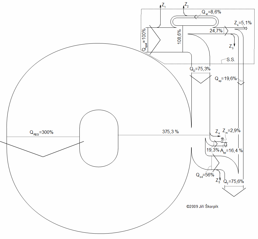
Effectiveness of transformation of thermal energy to work through the Stirling engine is shown the thermal efficiency on the coupling. The thermal efficiency on the coupling is defined as ratio between the shaft work and the amount of the input energy of unit with the Stirling engine. This efficiency is usually from 15 to 35 % for top Stirling engine, and very depends on the ratio between the mean temperatures of the working gas on the hot and cold side (on the boundary of the regenerator), this fact is described in the article 35. Energy balance of Stirling engine cycle. The efficiency is influenced by combustion part (if the unit contains the combustion part):
The diagram of the Stirling engine unit which has these parameters: fuel-biomass; the mean temperature of the working gas on the hot boundary of the regenerator tT=490 °C and the cold boundary tS=105 °C. S.S. boundary of combustion part of unit; Qspal [%] combustion heat; Qvz [%] heat for preheating of combustion air; Qspal-tuv [%] heat of exhaust gas that is used for heating or heating of domestic hot water; QD [%] heat transfered to heater; Qreg [%] amount of regenerated heat inside regenerator; Zm [%] mechanical losses; Asp [%] work of engine on coupling; QOd [%] heat transfered from cooler; Qv-tuv [%] rejected heat from engine (this heat can be use for heating or for heating of domestic hot water). Z1...5 [%] radiation losses, losses during cooling of engine block etc. Zk [%] flue loss.
References
Citation this page
©Jiří Škorpík, LICENCE
