An energy balance of a Stirling engine cycle can be do through an indicator diagram or trend pressure inside a Stirling engine which is calculated. Results of this energy balance are an input heat, a rejection heat, a regenerated heat, an internal work of the cycle and an internal thermal efficiency.
This article describes analytical calculation through equations, which are derived from the equations of the first law of thermodynamic. Through these derived equations can be calculated energy flows and theirs connection with others quantities.
Assumptions of solving
The equations of this energy balance are true under certain simplifying assumptions. Calculated results through these equation can vary from reality with increasing of differences between simplified and real processes: (1) Working gas is ideal gas. – (2) Stirling engine is perfect sealed. – (3) There is no pressure loss, pressure of working gas is same in whole working volume. (4) Regenerator has perfect thermal isolation. – (5) Pressure as function of angle of rotation (p(φ)), working volume on hot side as function of angle of rotation (VT(φ)) and working volume on cold side as function of angle of rotation (VS(φ)) are known. – (6) Stirling engine cycle is steady (the same cycle repeats).
Internal work of Stirling engine
The internal work of the engine is function the pressure and the working volume:

p [Pa] pressure of working gas; A [J] internal work of engine; VTV [m3] volume of cylinder on hot side; VSV [m3] volume of cylinder on cold side; AT [J] work of piston on hot side; AS [J] work of piston on cold side. Derivation of this equation is shown in the Appendix 463.
| AT | AS | A | ||
| 1382.2 | -506.01 | 876.19 |
Energy balance
Inside the Stirling engine is transformed heat to work. For this transformation are true the rules of heat cycle, it is means, only a piece of the heat input to the engine is transformed to work and others the heat is necessary rejected from the engine. For input and output of the heat to/from the engine between the working gas and a heat transfer surface must be a temperature gradient. This temperature gradient is vary during one cycle, because working gas temperature is changed also (see chapter Temperature change of working gas inside Stirling engine). Therefore in all internal sections of the engine the heat is inputted and outputted to/from working gas during one cycle. It is evident (from the principle of the Stirling engine) the heat balance during one cycle of the hot side is positive (the heat is inputted to the working gas) and the heat balance during one cycle of the cold side is negative (the heat is outputted from the working gas), the heat balance of the regenerator during one cycle must be neutral:

QT [J] heat balance of hot side during one cycle; ΔI [J] heat and work which needed for change of enthalpy of working gas inside engine during one cycle; QS [J] heat balance of cold side during one cycle; QR [J] heat balance of regenerator during one cycle. Derivation of these equations is shown in the Appendix 460.
The heat ΔI inputs through the cycle on the hot side and it increases of internal energy of the working fluid and other part of the cycle outputts on the cold side from the engine (through the temperature gradient between the hot and cold side). This heat decreasing a dimension capacity-rating of the heat transfer surface and a thermal efficiency of the cycle. On the other hand the heat ΔI develops the temperature gradient between the hot and the cold side even in for case of the regenerator with small capacity or for case it is not installation inside the engine. For cases isothermal processes on the hot and the cold side (e.g. Schmidt theory) must be the change of the enthalpy ΔI equal zero.
The internal work of the engine can be measured indirectly, e.g. by indication of the pressure of the working gas or by measuring work shaft (in this case is necessary to know mechanical losses of the engine). The internal work of the engine can be approximately calculated of the pressure trend by the procedure which is shown in article Stirling engine cycle (calculation without losses) or in article Losses in Stirling engines (calculation with losses).
Values of heats QT and QS can to get from a measuring of heat flow to/from the engine or it can be approximately calculated through an estimate the internal thermal efficiency:
Internal efficiency of Stirling engine
The internal thermal efficiency of the Stirling engine is ratio between its the internal work A and heat, which inputted to the working gas from a surroundings during one cycle QD* respectively this definition is the same as definition of efficiency of heat cycle, because inside engine is performed complet cycle. For the conditions, which are shown on List 1 can be descripted equality of heat flows:

QD [J] input heat to working gas from surroundings of engine during one cycle (input heat of engine); QOD [J] rejection heat from working gas to surroundings of engine during one cycle (rejection heat of engine).
The working gas gets some heat from regenerative surface of the engine (inside the engine) especially from the regenerator, but this heat is saved again to these surface during other part of the cycle, therefore this heat is not component of the input heat.
The internal thermal efficiency can be estimated through similarities of the Stirling engines similar construction:

ηt [1] internal efficiency of engine; C [1] Carnot efficiency ratio for Stirling engine* (C<1); τ [1] temperature ratio on border of regenerator; ηcar [1] Carnot efficiency ratio for temperature ratio. Derivation of these equations is shown in the Appendix 464.
Carnot efficiency ratio usually is in interval 0,65..0,75 offers exceptionally for case the best construction 0,8 [1, p. 99]. These values are derived from measurements on several the Stirling engines. An estimate of a value of the ratio C is function of the temperature of the working gas on hot border of the regenerator, the higher can be the expected higher coefficient C [1, p. 45].
| ηt | QT | QS | ΔI | ||
| 0.4117 | 2128.2 | -1252.0 | 746.03 |
Regenerated heat inside regenerator
The regenerated heat inside the regenerator can be calculated from a function which describes an amount of a heat transfered inside the regenerator of the working gas from a start of the cycle to any point of the cycle. The regenerated heat is equal of a difference between the maximum and the minimum of this function:

QR,x [J] amount of heat transfered inside regenerator of working gas from start of cycle (subscript 0) to any point of cycle (subscript x); QReg [J] regenerated heat inside regenerator during one cycle; κ [1] heat capacity ratio. Derivation of this equation is shown in the Appendix 469. This equations was first published in [3], [4], [5].
The enthalpy of the working gas inside the hot or the cold side in case isothermal processes is not changed respectively in Equation 5 is true IT,x=0; IT,x=0.
The amount of the heat QReg can be calculated approximately if the amount of the regenerated heat QReg is much more than the amount of the heat ΔI:
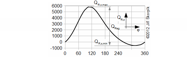
φ [°] angle of rotation.
During the solving of previous problem was neglected an influence of the change of enthalpy of the working gas on the hot and cold side respectively the heat ΔI. For actually case the influence of the change enthalpy is increased with decrease of the temperature ration τ respectively the ration between the heat QReg and the heat QD significantly decreasing and this procedure of the calculate used in Problem 3 increases its inaccuracy. This fact must be taken into account when designing the size of the regenerator:
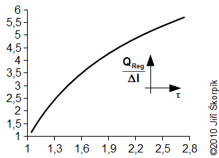
This curve is true for the cycle from the Problem 2 and Problem 3.
Entropy of working gas
An equation of a change of specific entropy of the working gas can be derived from First law of thermodynamics for closed system:

Subscript 0 denotes the start of cycle and subscript x denotes any point of cycle. cv [J·kg-1·K-1] specific heat at constant volume; r [J·kg-1·K-1] gas constant of working gas; s [J·kg-1·K-1] specific entropy. Derivation of this equation is shown in the Appendix 474. This equation was first published in [3].
Through last Equation can be constructed a T-s diagram of the cycle. From T-s diagram of cycle can be identified losses of the cycle. In praxis can be measured perfectly only pressure of the working gas as function of angle of rotation. Exact amount of the working gas inside of the engine and its exact mean temperature of the working gas is impossible to measure. Therefore is constructed Θ-s diagram*, where Θ is ratio between the mean temperature of working gas inside of the engine and maximum temperature of the working gas inside of the engine. The Θ-s diagram can be constructed only from the measured pressure.
Θ-s diagram, which is designed from a measurement, can show losses and weaknesses of the engine:
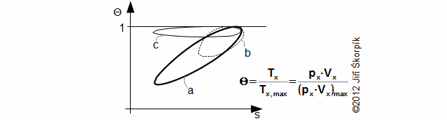
a ideal Θ-s diagram; b Θ-s diagram of an engine with small capacity of regenerator; c Θ-s diagram of an engine with leakage of piston rings. This equation was first published in [6].
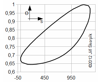
The fact, minimal entropy corresponding with the state p0, V0 is only a random.
Amount of working gas inside engine
The amount of the working gas inside of the Stirling engine can be computed by the equation of state [2, p. 67 (cz)] for each working volumes. The amount of the working gas is computed for a known state of the working gas. If real mean temperature of the working gas inside individual volumes is not known, then can be use of computed of temperature change of the working gas inside Stirling engine:
| m | ||
| 5.9234 |