| Turbomachinery |   |
This article follows the article Essential equations of turbomachines and Energy balances of turbomachines. In these articles are defined quantities a specific shaft work lu and a specific internal work of turbomachine stage ai.
The specific internal work of stage is corresponded work of the working fluid inside stage and it is calculated from difference of stagnation states between the inlet and the exit of stage. The specific work shaft is corresponded work of the working fluid transformed to the torque of the shaft and it is calculated from a velocity triangels in front of and behind the rotor and from a friction between the rotor and the working fluid so called rotor friction losses:
The specific shaft work of real machines is influenced by friction between the rotor and the working fluid so called rotor friction losses:
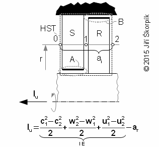 |
1.318 Difference between work shaft and internal work of stage. HST volume of stage; r [m] radius; lu [J·kg-1] specific work shaft of stage on radius r(1); c [m·s-1] absolute velocity; w [m·s-1] relative velocity; u [m·s-1] circumference velocity; ar [J·kg-1] rotor friction losses of stage(2); lE [J·kg-1] specific work of working fluid during flow through rotor blade row without rotor friction losses; ai [J·kg-1] specific internal work of stage; A, B areas of development friction losses under friction between rotor and working fuid. S stator blade row; R rotor blade row. |
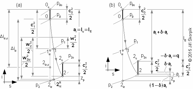
The rotor friction losses of the stage is a consumed work, which is transformed on heat. This friction heat heatings the working fluid in surrounding:

From equation of specific internal work of turbomachine is evident heat δ·ar increases reajected heat to surroundings and heat (1-δ)ar increases internal heat at the exit of stage ue respective enthalpy ie. This decreases the specific internal work and the specific shaft work same, therefore for now be can lu=ai.
The conclusion of the previous paragraph was formulated on the assumption that the working fluid flow only through blade passage at development only the profile losses and rotor friction losses without the other losses of the stage. But the turbomachine stage is a classically engineering product, which usually is not perfectly, therefore there are other losses(3) inside stages also e.g. a portion of the working fluid can flow outside the blade passages (leaks, construction gap) etc.:
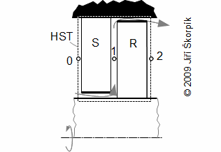 |
3.1089 Example of flow through a leak of a turbine stage. |
In computing practice, the term spedific shaft lu means the internal work of the stage without the influence of other losses (perfectly tight stage and without losses occurring at the root and tips of the blades, we can also speak of a stage with infinitely long blades). The internal specific work of stage ai is then the actual specific work of stage including all losses (lu>ai).
For turbine stages be can constructed i-s diagram according the chapters Adiabatic expansion inside heat turbine, Polytropic expansion inside heat turbine:
For stages of working machines be can constructed i-s diagram according the chapters Adiabatic compression inside compressor, Polytropic compression inside compressor:
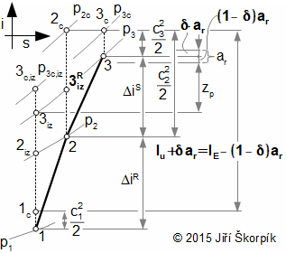 |
5.719 i-s diagram of compressor stage on radius r. |
Total energy balance of the stage in i-s diagram shows all losses, enthalpy and the work of the working fluid at the exit for case ideal mixing:
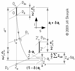 |
6.319 The specific internal work of a turbomachine stage on a tested radius r. zst [J·kg-1] total losses of stage. The other losses of stage increases enthalpy from state 2 on the state 2' at the exit. |
If the other losses influences state of the working fluid inside core flow at exit first blade row then it can be influenced proces inside second blade row:
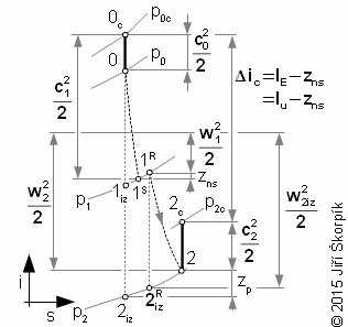 |
7.947 Influence the other losses on the work shaft. zns [J·kg-1] specific loss through leaks of stator. This is case from Figure 5 (ar≈0 J·kg-1). The flow inside core of stage is influenced by leaks on the stator blade row in this case. The working fluid from seal of the stator increases enthalpy at the inlet rotor blade row. |
The shape of i-s diagram of flow through blade row of the stage corresponds to construction of stage. The i-s diagrams axial and diagonal stages are shown in article 19. Design of axials turbomachine stages, and in article 20. Design of radials turbomachine stages are shown i-s diagrams of radial stages.
For cases turbomachines without casing the flow mass of the working fluid beside the stream-tube of rotor are not included to the other losses zost.
Two efficiencies of the stage are defined because two work of the stage are defined:

For cases stages of working machines is usually defined the effective efficiency respectively isentropic efficiency of the stage. These efficiency are connected with static state of the working fliud at isentropic processes:

The sum of the energy balance all stages and the energy balance of other section of the turbine must be equal the energy balance of the stage section of the turbine as one entire:
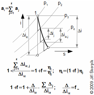 |
10.116 A multistage adiabatic expansion inside turbine. ηj [-] mean internal efficiency of individual stages; 1+f [-] reheat factor (coefficient of the re-usable heat, 1,02 to 1,04 according [3]); Δ [J·kg-1] re-usable heat of turbine; 1+f∞ [-] reheat factor for case heat turbine with infinite number of stages; z [-] numbers of stages. The efficiency of stage section of multi-stage turbines ηi e.g. multi-stage steam turbines is higher than ηj of individual stages. These equation are derived for the same the enthalpy difference for all stages and for adiabatic expansion. For better illustration is not drawn the absolute velocity c. The derivation of this equation is shown in the Appendix 116. |
It is evident, a portion of the heat from the loss processes inside previous stage is used inside next stage during expansion. Only the heat from the loss processes inside last stage of the heat turbine are not used. The re-usable heat influences as well as flow through one stage, because a portion of stator losses be can use in the rotor etc.
In case multi-stage turbocompressors, the resulting compression is composed of several sub-compression, their number is equal number of the stages inside turbocompressor:
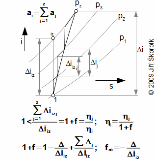 |
11.121 An multistage compression inside turbocompressor. 1+f [-] preheat factor (coefficient of additional losses); Δj [-] additional losses of one stage; 1+f∞ [-] preheat factor in theoretical case turbocompressor with infinite number of stages. The efficiency ηi of multi-stage turbocompressor is less than ηj. These equation are derived for the same the enthalpy difference for all stages and for adibatic compresion. For better illustration is not drawn the absolute velocity c. The derivation of these equations is shown in the Appendix 121. |
It is evident, the internal losses of one turbocompressor stage reduces the internal efficiency of next stage. The additional losses influences as well as flow through one stage, because losses of rotor increases losses of stator etc.
ŠKORPÍK, Jiří. Vztah mezi obvodovou a vnitřní prací stupně lopatkového stroje, Transformační technologie, 2009-10, [last updated 2018-02-26]. Brno: Jiří Škorpík, [on-line] pokračující zdroj, ISSN 1804-8293. Dostupné z https://www.transformacni-technologie.cz/14.html. English version: Relation between specific shaft work and internal work of turbomachine stage. Web: https://www.transformacni-technologie.cz/en_14.html.