LOSSES IN STIRLING ENGINES
The power output on shaft of the Stirling engine is influenced by losses. These losses can be separated on thermodynamic losses and mechanical losses. The thermodynamic losses are influencing a shape of p-V diagram, the mechanical losses are caused through friction in mechanisms (in bearings, between piston rings and a cylinder atc.). So, there are other losses, which may not influence on the power output of the engine. There are other losses also , which may not influence on the power output of the engine, but can influence fuel consumption or a heat (efficiency of heat source, conduct of heat inside block engine etc.), this type of losses is described in [5, s. 105].
Similarities of Stirling engines
For base design of the Stirling engine can be used theories of model/dimensionless quantity similar like for a design other machines. The most popular dimensionless quantity of the Stirling engine is Beale number* through it can be predicted the power output of the engine (there are other the dimensionless quantities of the Stirling engine but no use very). For start of calculation can be knew a displacement of the engine on the hot side, a operating speed, a mean pressure of working gas and a heater temperature (outside surface):
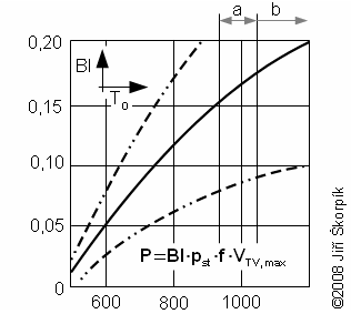
Bl [1] Beale number; P [W] power output of engine; f [Hz] frequency of engine speed; pst [MPa] mean pressure of working gas inside engine; TO [K] mean temperature of working gas on hot side; VTVmax [cm3] cylinder volume on hot side. a limit for conventional stainless steel of heater of Stirling engine; b border between high-alloy steel and ceramic materials. This function was created for cooler temperature 65 °C and be can use for all types of the Stirling engines and species of working gas.
This method was described by Walker Graham in the year 1979 [2], [3, p. 57]. Name this method was quoted according Williama Beala, which as first man was observed similarities of Stirling engines during his work in Sunpower, Inc. (USA; Ohio; Athens) where he tested of many Stirling engines (more information about historian connections on [5, p. 99]).
Beale number of the engine is near the upper line with smaller death volume and lower temperature of working gas on cold side. Beale number of the engine is near the down line with bigger death volume and higher temperature of working gas on cold side.
Thermodynamics losses of Stirling engine cycle
The Stirling engine cycle is influenced by leakage of piston rings, conduct of heat from/to working gas to/from surroundings, conduct of heat in a matrix of regenerator and pressure drop, which are developed during flow of working gas. With increase of these losses is increased different between real cycle and ideal comparing cycle. For calculation of p-V diagram of the Stirling engine cycle are used analytical or numerical methods:
In the first step is calculated p-V diagram of Stirling engine cycle for case constant polytropic index inside all working volume through formulas, which are showed in article 34. Stirling engine cycle. This diagram includes some types of losses, which the Schmidt theory; [5, p. 71]; [3, p. 40] does not (the losses of a different between isothermal process and real process). In next step is refined p-V diagram according predicting leakage of piston rings, which has significant influence (the description of this loss is showed in next chapter). The work and efficiency of the engine can be refined with taking on other losses according [5, p. 105], [3].
This method includes real conditions (heat transfer coefficients; change of thermo-mechanical properties of working gas) and also losses (losses conduct the heat from/to surroundings; losses leakage of the piston rings etc.). This method is difficult on to enter initial and boundaries conditions and there is problem with calculation any losses due to convergence solve yet. Khamid Mahkamov is one of the first man, which made complete CFD model of the Stirling engine cycle including combustion system, this computation be was checked on real engine (γ-configuration, 0,5 kW) [1, p. 96].
This paper describes only the calculation of the p-V diagram for case analytical method. From an experience and a measurement of the Stirling engines clearly shows, that greatest influence on change of the shape of p-V diagram has the polytropic exponent and the leakage of piston rings (it deforms p-V diagram from all sides). An influence others losses* on the shape of p-V diagram can be negligible.
Great influence can have the pressure loss also. In this case is improper design of the engine (high flow speed). Therefore is calculated with pressure loss on work only, and for calculation p-V diagram the pressure loss is not significant.
Losses through leaks of piston rings
The leaks of piston rings has major impact on work of Stirling engine, it was shown the practical experiences with construction of Stirling engines and its operating. It often is the biggest technology problem during developing of new engine. The leakage of pistons is being caused through roughness of cylinder surface, difference between diameter of cylinder and piston ring and vibration of engine during operate.
There are piston rings on hot side and cold side. Piston rings are separated of working volume of engine from the volume under pistons.Pressure of working gas inside working volume is changed during one cycle. If the volume under piston is not working volume then it should be so big for approximate constant pressure here. The working gas is being flowed through the leaks of piston rings from working volume to under the pistons if pressure of working gas is higher than pressure under pistons and on the contrary. It means that the mass of working gas is not constant in working volume of engine.
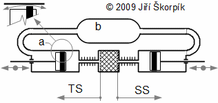
a piston ring; b volume under pistons and buffer tank; TS hot side of engine; SS cold side of engine. The figure is shown outflow/inflow of working gas through piston rings during one cycle.
The mass of working gas is varied between a maximum and a minimum value during an cycle. Therefore the cycle can be divided into two intervals. The mass of working gas is decreased on the one interval of cycle (working gas is flowing from working volume) and is increased on the next interval of cycle (working gas is flowing to working volume). This change of mass of working gas is influenced of p-V diagram shape. Strictly speaking, maximum pressure of cycle is lower, minimum pressure is higher than for case absolute seal of piston rings. The change of pressure is not large usually, nevertheless reducing of the internal work of the Stirling engine is big. This big reduce is caused a shift of maximum pressure left in p-φ diagram. It means that that the maximum pressure of working gas is reached earlier for case a leaks of piston rings than for case absolute seals piston rings:
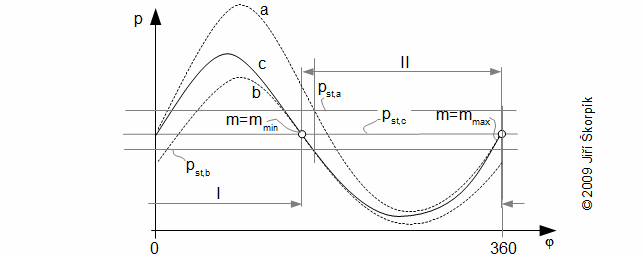
a p-φ diagram for case m=mmax; b p-φ diagram for case m=mmin; c diagram of engine with a leaks through piston rings (mass of working gas is changed on interval mmax..mmin). p [Pa] pressure of working gas in working volume; pst [Pa] mean pressure; φ [°] angle of shaft rotation; m [kg] mass of working gas in working volume. I mass of working gas is decreasing; II mass of working gas is increasing.
This diagram is for case α-configuration Stirling engine and for constant pressure under piston. In case double-acting engine is curve c more complicated, because the pressure under piston is changed.
The leak through piston rings is defined as ration between maximum change mass of working gas and mass of working gas in working volume for case absolute seals of piston rings:

μ'' [1] mass ratio; Δm [kg] mass of working gas outflow/inflow to/from under piston; m [kg] mass of working gas in working space for case absolute seals piston rings. For good sealing engine is mass ratio on interval μ''<0,02..0,05* (it is equivalent PTFE rings and working gas He). The engines with higher μ'' can be called as no-sealing. The leakage of engine is measured by stop run of machine more better for different pressure and temperature or it can be computed through method which is described in next paragraphs.
There is other leaks in the engine respectively a connection of working volume with volume under pistons. This connection is function construction.
During comparisons the measured p-φ diagram with computed p-φ diagram by method that is shown in article 34. Stirling engine cycle was found a similarity [7, s. 63]. The shape of curve of pressure was similarity to the shape computed of pressure, but it is shifted on difference Δφ and it is flattened around pressure extremes about Δp. On the base these knowledges was created simplify assumptions of solving Stirling engine cycle with leaks through piston rings: (1) Pressure inside Stirling engine for case absolute seals of piston rings (ideal cycle) is equaled. – (2) Pressure under pistons is constant and equal to the mean pressure of cycle. – (3) Leaks through piston rings is brought shift ideal cycle on angle Δφ. – (4) Different of pressure is directly proportional to the difference between the pressure and medium pressure (linear model). – (5) difference pressure between maximum pressure for case ideal cycle and maximum pressure for case real cycle is equal half of total mass loss of working gas Δm. – (6) The working gas outflow/inflow from/in working volume through piston rings only. – (7) The working gas outflow/inflow from/in working volume is not brought change temperature of working gas and its change polytropic index. – (8) Cycle is steady (the same cycle repeats).
If the pressure is function of rotation of shaft p(φ) then the shift of pressure about angle Δφ is function of rotation of shaft and the shift p'(φ+Δφ). The shift Δφ is computed from minimum of mass of working gas in working volume:
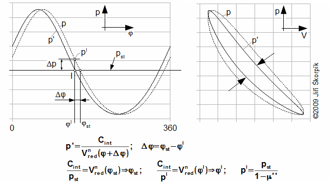
p pressure for a case absolute seals of piston rings; p' shift of pressure about the difference Δφ; Cint [Pa·m3] integration constant; n [1] mean value of polytropic index; Vred [m3] reduced volume see article Stirling engine cycle; V [m3] working volume of engine. The shift of p-φ diagram about angle Δφ is brought a narrowing of p-V diagram and a decreasing the internal work of the engine. Derivation of this equation is shown in the Appendix 483.
The Vred equation is function of type of mechanism. The most frequently is used crank shaft and in this case be can derived equation of Δφ strictly at some simplifying assumptions:

τ [1] temperature ratio between hot and cold side of regenerator; τR [1] temperature ratio between temperature on hot side of regenerator and mean temperature in regenerator; S [m2] area cross section of cylinder on hot side T and area cross section of cylinder on cold side S; α [rad] phase angle of hot side variation of volume to cold side volume. The signs is the same as the chapter Pressure profile inside Stirling engine with crankshaft. These equations was derived for case sinus movement of pistons. Derivation of this equation is shown in the Appendix 238.
The alternates change of working gas in working volume causes a decrease pressure ratio, too. The decrease pressure ratio according to Assumption (4) is equal and directly proportional to pressure difference and mean pressure:
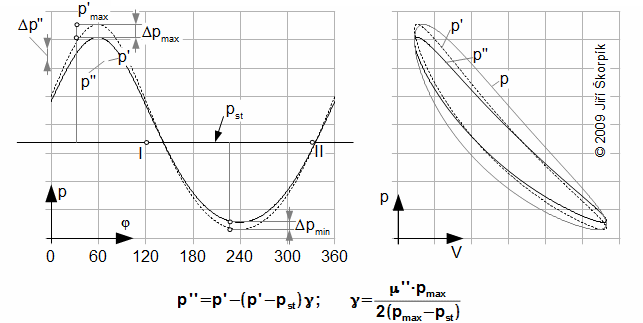
γ [1] the proportionality factor of change of pressure; p'' [Pa] the estimate curve of pressure in case the leaks of piston rings. Derivation of this equation is shown in the Appendix 484. This equation was first published in [7], [8].
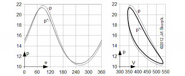
It is evident, that wear of piston rings is brought significant decrease of work of cycle, therefore is reasonable create the internal work of the engine as function μ'' similar as in next problem:
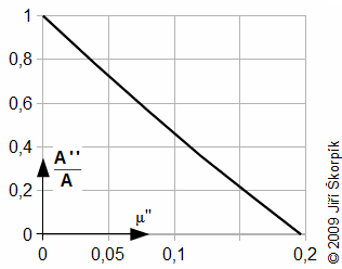
A [J] internal work of the engine for case absolute seal of piston rings; A'' [J] internal work of the engine for case the leakage of piston rings.
From definition of difference Δφ is evident for pst=const. and μ''=const. will be difference is greater the larger the death volume.
From results of last problem is can deduced that the influence of piston rings on work of cycle is big. Already for a leakage 13% the internal work of the engine is reduced about 50%, for a leakage 20 % engine is not operational really. The leakage is function roughness of cylinder surface, a deformation of piston rings and vibration of engine. The size of leakage can be computed approximately from equation of mass flow rate through the nozzle:

(a) equation is true for n=const.; (b) condition for true of equation. μ [1] flow coefficient*; A [m2] equivalent of flow area (leakage); v [m3·kg-1] specific volume; n [s-1] speed rotation; χm [1] flow factor; κ [1] heat capacity ratio; ε [1] pressure ratio (in Equation (a) is Ludolphian number); ε* [1] critical pressure ratio of working gas. The equations was derived for ideal gas and lossless flow*. Derivation of this equation is shown in the Appendix 887.
Flow coefficient taken into account of flow losses through flow area. Flow coefficient is function of roughness and shape of flow area. Flow coefficient for ideal jet is μ=1. For cylinder jet is μ≐0,6..0,9-as function ratio between diameter and length. For leakage between piston ring and surface of cylinder is μ probably smaller.
The region around piston rings is being cold and temperature of working gas under piston is approximate constant, therefore it is not necessary doing compute of leakage for each piston ring separately.
From Equation 6. is evident that mass flow is function of specific volume respectively temperature. The working gas on hot side is being flowed through piston rings is more hot than working gas, which is being flowed return. It is being brought a return of more working gas to working volume in part II of cycle than was outflow in part I of cycle. Therefore is drilled to piston small a nozzle* (about tenth of millimeter-diameter is function VVTmax and pressure ratio), which is brought higher leakage and parallel is done balance between outflow/inflow of working gas. On hot side is situation opposite, but difference of temperature is not big and the unbalance mass flow on hot side is more significantly.
The nozzle is made on place where there is not big temperature difference between gas over/under piston-usually on cold side.
| Δm | A | ||
| 0.237 | 1,1452 |
This method of compute of Stirling engine cycle for case a leakage of piston rings is based from measurements of experimental engine from 2002 to 2012 years and these experiments is made company Tedom a.s. [4] respectively company Strojírny Bohdalice, a.s. [6], which in this development is continued. Leader this project is Josef Brož. Some measurements are accessible in [7].
References
Citation this page
©Jiří Škorpík, LICENCE